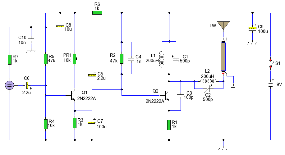


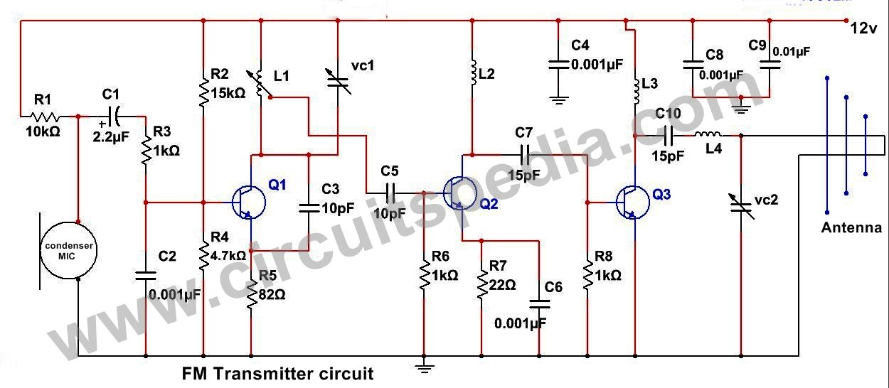

Long Range FM Transmitter. The power output of many transmitter circuits are very low because no power amplifier stages are incorporated. The transmitter circuit described here has an extra RF power amplifier stage, after the oscillator stage, to raise the power output to milliwatts. FM, FM transmitter, FM transmitter circuit diagram, FM useing transistor, long range fm transmitter Long range FM transmitter Principle of this project: Parts 1. BC547 transistor 3 in this number! 10pf capacitor whose code is 10! Long range FM transmitter circuit diagram. T1 is used as an oscillator stage to deliver a low power stable frequency. use the 10k linear potentiometer like this: if you trim down, towards ground, the freq. will drop and if you adjust it toward it will rise. For Long Range use a Yagi antenna. The output is fed to a coaxial cable (generally used for cable TV ) which is nearly matched to the Yagi antenna (though 300 Ohms) impedance of 75 ohms by trimmer TR 2 of the tuned circuit for maximum power delivery to the load ie the Yagi GP antenna. long range fm transmitter Hello friends, We know that building of Fm transmitter for first time is quite hard and we get confused about the components, parts, design, pcb, transmission frequency, inductor value and making of inductor, polarity of the capacitor and many things. Long range FM transmitter Electronics Circuits Hobby. Long range FM transmitter Electronics Circuits Hobby. This transmitter circuit uses the direct method of FM generation. The circuit built around transistor T1 (BF494) is a basic lowpower variablefrequency VHF oscillator. A varicap diode circuit is included to change the frequency of the transmitter and to provide frequency modulation by audio signals. Long range FM transmitter Electronics Circuits Hobby. Discover ideas about Hobby Electronics range fm transmitter circuit diagram electronics, fm transmitter and receiver This is a simple wireless FM transmitter circuit which uses RF communication to transmit the medium or low power FM signal. Construction Procedures for the proposed long range transmitter circuit A simple printed circuit technique is employed, with most components fixed directly to the print t side of the board. There are very few holes to be drilled and the units may be secured. Long Range FM transmitter Circuit The power output of most of these circuits are very low because no power amplifier stages were incorporated. The transmitter circuit described here has an extra RF power amplifier stage, after the oscillator stage, to raise the power output to milliwatts. Long Range FM Transmitter Circuit diagram. The use of transmitters which have a more powerful output than the fleapower are sometimes required when there are many obstacles in the path of the surveillance transmitter and monitoring station receiver, or the distance between them is too far so as to make a low powered device feasible. This is long range fm transmitter circuit in VHF range. As Figure 1 Sonar with up to 2 watts, when used with a supply voltage of about 24V. In the case of applications typically do not want a high transmission. A FM transmitter can cover maximum distance, Here showing a Long Range FM Transmitter Circuit diagram that can cover the distance upto 5 km and with the power of 1 w. Here presenting a small powerful circuit of a FM transmitter which operate with 12v dc. Long Range FM Transmitter Circuit diagram: The circuit built around transistor T1 (BF494) is a basic lowpower variablefrequency VHF oscillator. A varicap diode circuit is included to change the frequency of the transmitter and to provide frequency modulation by audio signals. Build a Simple Solar Powered Long Range FM Transmitter Circuit Diagram. This is very stable, harmonic free, long range fm transmitter circuit which can be used for fm frequencies this one is unique in that it runs completely on solar power. Long Range FM Transmitter Circuit. The FM transmitter circuits are generates the output power depending on power amplifier. If any transmitter circuit have consist Rf amplifier stage, oscillator stage then the output power of that ckt provides good power signal. FM TRANSMITTER CIRCUITS THE BIG LIST observe the schematic diagram before you build this circuit. Long Range FM Transmitter This is one of the low cost circuits you can make to build a long range transmitter. The basic working is same its a two stage transmitter. This longrange FM radio transmitter has an additional RF power amplifier stage, after the oscillator stage. The extra RF power amplifier used to strenght up the power output to become milliwatts. Long range FM Transmitter Circuit 9v to 12v Can be able to manufacture the range of two kilometers This circuit shows how to build a supersensitive, minipowered FM transmitter consisting of a RF (radio Frequency) oscillator section interfaced with a high sensitivity, wide passband audio amplifier and capacitance mike with a builtin FET (Field Effect Transistor) that modulates the base of the RF oscillator transistor. The FM transmitter circuit (Frequency modulation) is a circuit made up of a single transistor or a BJT. In a wireless communication, the (frequency modulation) FM carries the data or information by changing the frequency of the carrier wave as per the information or a message signal. Friends in this video I will show you FM Transmitter. How To Make A Long Range FM Transmitter. Friend it is a very simple circuit project and. The aim of this project is to develop a low cost long range FM Transmitter with audio modulation. The FM transmitter has 3 stages, A (VFO) Variable frequency Oscillator (30 mw), a class C driver stage (150 mw) and a class C final power amplifier (1 Watt). FM Transmitter Circuit Principle: FM transmission is done by the process of audio pre amplification, modulation and then transmission. Here we have adapted the same formula by first amplifying the audio signal, generating a carrier signal using an oscillating and then modulating the carrier signal with the amplified audio signal. Here is the circuit diagram of an easy to build long range AM transmitter circuit based on three transistors. With correct tuning and a matching antenna, the transmitter can deliver signals up to a distance of 2 kilometers. Most simple FM transmitter circuit diagram Jaseem vp September 12, 2012 This is the most simplest and single transistor FM wireless transmitter circuit that ever posted in CircuitsGallery. This article gives the FM transmitter circuit schematics with necessary explanation. The main component used here is the VMR6512 IC which is a highly integrated FM audio signal (HiFi. This is very stable, harmonic free, long range fm transmitter circuit which can be used for fm frequencies between 88 and 108 MHz. This can cover 5km range (long distance). It has a very stable oscillator because you use LM7809 stabilizer which is a 9V stabilized power supply for T1 transistor and for frequency adjustment that can be achieved by using the 10K linear potentiometer. FM transmitter circuit The circuit built around transistor T1 (BF494) is a basic lowpower variable frequency VHF oscillator. A varicap diode circuit is included to change the frequency of the transmitter and to provide frequency modulation by audio signals. Hello, As you might have noticed there are some HAM radio amateurs on this forum. @recklessrog, @dendad and I are already a couple. Bertus This is a long range stable FM transmitter circuit. The circuit is using a LM2950 5V voltage regulator IC comes in TO 92 transistor package, which will provide a stable 5V to the oscillator till the 9V battery runs down to 5. 5 volts, due to which the oscillator becomes frequency stable. Here is a good long range FM transmitter circuit diagram with minimum components but will give a good result. This FM RF transmitter circuit has two stages first oscillator stage and second RF amp stage. The proposed long range transmitter circuit really is very steady, harmonic free design which you can use with standard fm frequencies between 88 and 108 MHz. Long Range FM Transmitter Circuit Diagram Once you have established a working frequency of the oscillator in the range MHz, you can further build up the buffer that is. Circuit diagram for Long range FM Transmitter On the same core make 2 turns of 1 mm enamelled copper wire close to L1 and that will be L2. Inductor L2 couples the FM signal to the antenna. Simple FM Transmitter Circuit audio. We do not have a RFAmplifier in our circuit, but it can be added if you need to achieve a higher range. Circuit Diagram: The Circuit Diagram of this Simple FM Transmitter is shown in the image below. Long range fm transmitter circuit diagram This is very stable, harmonic free, long range fm transmitter circuit which can be used for fm frequencies between 88. This circuit is a circuit diagram fm transmitter. This circuit is somewhat different from the previous fm transmitter circuit. Transmitter circuit described here has the additional RF power amplifier stage, after the oscillator stage, to increase the power output of milliwatts. How to make a long range FM transmitter at low cost. The use of transmitters which have a more powerful output than the fleapower are sometimes required when there are many obstacles in the path of thesurveillance transmitter and monitoring station receiver, or thedistance between them is too far so as to make a low powered devicefeasible. Long range, very stable, harmonic free, FM transmitter circuit which can be used for FM frequencies between 88 and 108 MHz. With good antenna transmitter can cover 5km range. It has a very stable oscillator because it uses LM7809 voltage regulator which is a. This one is a high power long range (use yagi antenna) FM Transmitter that provides very good frequency stability in about 1km range and very good microphone sensitivity. It can be used inside guitars, as a part of remote control systems or in other similar applications. This long range FM transmitter electronic project is a very simple and powerful transmitter circuit with a range up to 1 kilometer in open air. This long range FM transmitter uses an RF transistor in its output stage and two BC547s for the first two stages. This is very stable, harmonic free, long range fm transmitter circuit which can be used for fm frequencies between 88 and 108 MHz. This can cover 5km range (long distance). It has a very stable oscillator because you use LM7809 stabilizer which is a 9V stabilized power supply for T1 transistor and. Licious Fm Transmitter Circuit Rf Circuits Diagram Long Range Making A Of The Crystal Mw Transmitter This is very stable, harmonic free, long range fm transmitter circuit which can be used for fm frequencies between 88 and 108 MHz. This can cover 5km range (long distance). It has a very stable oscillator because you use LM7809 stabilizer which is a 9V stabilized power supply for T1 transistor and for frequency adjustment that can be achieved. Free Electronic Circuits, Schematic Diagram, Circuit Diagrams. electronics diagram, circuit design, circuit diagram, circuit Long Range FM Transmitter This is one of the lowcost circuits you can make to build a longrange transmitter. The basic working is the same its a two stage transmitter. The basic working is the same its a two stage transmitter. Long range fm transmitter circuit diagram and schematic at low cost using very simple components. This is a simple radio transmitter circuit any one can try. Looking for Latest Electronics Project Kits?.