


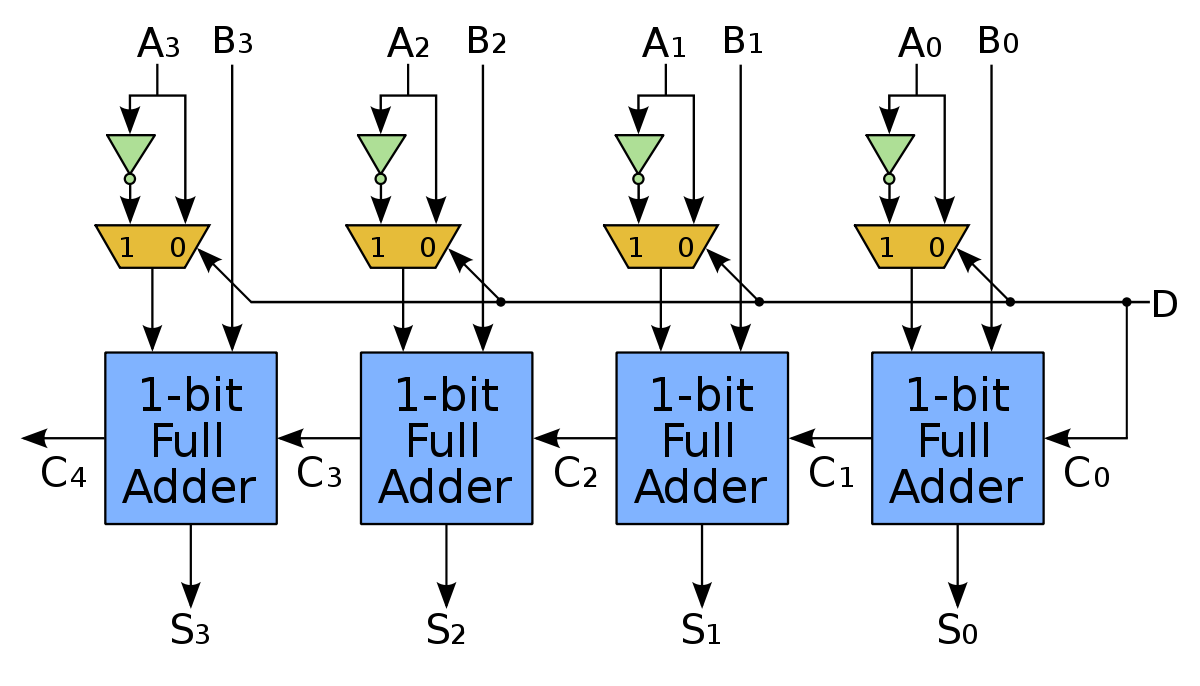

To demonstrate the operation of the IC 7483 (4bit binary fulladder and subtractor, having input and output carry bits). Any two to four bit, binary numbers (0000 and 1111) can be added or subtracted using complementary techniques. Implementation of 4bit parallel adder, using 7483 IC. LEDs and 220 Ohm resistros Theory: Adder: An adder is a logic circuit which adds two or three bits at a time and give sum and carry as the result. Parallel Adder: A nbit parallel adder can be constructed using number of full adders circuit connected in parallel. In digital circuits, an addersubtractor is a circuit that is capable of adding or subtracting numbers (in particular, binary). Below is a circuit that does adding or subtracting depending on a control signal. It is also possible to construct a circuit that performs both addition and subtraction at the same time. That The 4bit parallel adder circuit means when a 4bit and the controlled inverter subtraction operation, which together constitute the 4bit produces a negative value, is addersubtractor composite unit done by this circuit it gives a as shown in the figure. Adder(CLA), Carry Generate Carry Propagate, Lect41 Duration: 10: 28. University Academy FormerlyIP University CSEIT 10, 491 views I am designing a 4bit addersubtractor circuit using CMOS technology. The instructions I was given for the design portion are as follows: Given two 4bit positive binary numbers A and B, you are to design an addersubtractor circuit to compute (AB) or (AB), depending. Parallel adders are digital circuits that compute the addition of variable binary strings of equivalent or different size in parallel. The schematic diagram of a parallel adder is shown below in Fig. Cout example of a parallel adder: a 4bit ripplecarry adder. It is composed of four full adders. Addersubtractor is a digital circuit that can do both addition and subtraction: signed, unsigned, 2's complement, with overflow. The circuit has a Mode switch that allows you to choose between adding (M0) and subtracting (M1). To understand why this circuit works, lets review binary addition and binary subtraction. To study adder and subtractor circuits using logic gates. To construct and test various adders and subtractor circuits. Theory: Adders: Adder circuit is a combinational digital circuit that is used for adding two numbers. an N bit parallel adder, there must be N numbers of full adder circuits. A ripple Binary Parallel AdderSubtractor The addition and subtraction operations can be done using an AdderSubtractor circuit. The figure shows the logic diagram of a 4bit AdderSubtractor circuit. The circuit has a mode control signal M which determines if the circuit is to operate as an adder or a. CS302 Digital Logic Design The circuit that checks if the output of the first Adder has exceeded 9 is a simple combinational circuit with the function table specified. The input carry to the adder isC0 and it ripples through the full adder to the output carry C4. 4 BIT BINARY SUBTRACTOR: The circuit for subtracting AB consists of an adder with inverters, placedbetween each data input B and the corresponding input of full adder. We have seen parallel adder circuit built using a cascaded combination of full adders in the article Parallel Adder. Likewise in the article on Parallel Subtractor we have seen two different ways in which an n bit parallel subtractor can be designed. In this 50 mins Video Lesson: Parallel Ripple Adder, Look Ahead Carry Fast Adder, IC 7483, BCD Adder using IC 7483, Subtractor using IC 7483, Adder Subtractor using IC 7483, and other topics. 9 FOURBIT BINARY PARALLEL ADDER. In the preceding section, we discussed how two binary bits can be added and the addition of two binary bits with a carry. In practical situations it is required to add two data each containing more than one bit. A full adder adds binary numbers and accounts for values carried in as well as out. A onebit fulladder adds three onebit numbers, often written as A, B, and C in; A and B are the operands, and C in is a bit carried in from the previous lesssignificant stage. The full adder is usually a component in a cascade of adders, which add 8, 16, 32, etc. the carry cant be converted using boolean algebra but paying attention to function where NAND0 if both inputs are 1 otherwise it's 1 so we need to avoid settin our NANDs while SUM 9 obvously we need 1 NAND to invert a bit for that This is an 8bit parallel addersubtractor. This circuit adds in the same way as the adder in Fig. but subtracts using the twos complement method described in Digital Electronics Module 1. Component: Four Bit Parallel Adder 4bit Parallel Adder Using 7483 Ic Four Bit Parallel Adder Truth Table 4 Bit Parallel Adder Verilog Code and Components. 4 bit parallel adder and subtractor theory. 4 bit parallel adder verilog code. 4 bit parallel adder wikipedia. Parallel subtractor pdf Parallel subtractor pdf Parallel subtractor pdf DOWNLOAD! parallel addersubtractor using 7483 parallel subtractor theory 4 bit number Y from 4. In digital osprey men at arms 181 austrian army of napoleonics war 2osp circuits, an addersubtractor is a. MC B 4Bit Full Adder The MC B 4bit full adder is constructed with MOS PChannel and NChannel enhancement mode devices in a single It is useful in binary addition and other arithmetic applications. The fast parallel carry output bit allows highspeed operation when used with other adders in. Design of Parallel In Serial OUT Shift Register System Design using Loop Statements (Behavior Mode Sample Programs for Basic Systems using VHDL Design of 4 Bit Adder cum Subtractor using Loops ( Design of 4 Bit Subtractor using Loops (Behavior M Design of 4 Bit Adder using Loops (Behavior Modeli To realize the adder and subtractor circuits using basic gates and universal gates b. To realize full adder using two half adders Theory: Half Adder: A half adder is a combinational circuit that performs the sum of two binary digits (A, B) to give a maximum of two binary. Unlike the Binary Adder which produces a SUM and a CARRY bit when two binary numbers are added together, the binary subtractor produces a DIFFERENCE, D by using a BORROW bit, B from the previous column. Then obviously, the operation of subtraction is the opposite to that of addition. Theory: IC 7483 is a 4 bit adder. In binary, subtraction can be performed by using 2's complement method. In binary, subtraction can be performed by using 2's complement method. In this method negative number is converted into its 2's complement and it is added to the other number. I would like the give a more general answer to this question for any positive natural number of bits. Lets call the last Carry output C1, the second to last Carry output C0, the sum sign output S0 and the signbits of A and B respectively A0 and B0. Parallel Adder Subtractor The operations of both addition and subtraction can be performed by a one common binary adder. Such binary circuit can be designed by adding an ExOR gate with each full adder as shown in below figure. EXPERIMENT: 1 LOGIC GATES AIM: To design and set up the following circuit using IC 7483. i) A 4bit binary parallel adder. ii) A 4bit binary parallel subtractor. To realize a subtractor using adder IC 7483 COMPONENTS REQUIRED: IC 7483, IC 7486, Patch Cords IC Trainer Kit. THEORY: The Full adder can add singledigit binary numbers and. Construct and test the full adder and full subtractor that you designed in Part 3 of the preliminary work using ICs connected onto a breadboard. 4Bit Parallel Adder Subtractor DB19 Table of Contents 1. Experiment 1 13 To study parallel adding of 4 bit with carry. Experiment 2 16 To study parallel subtraction of 4 bit with carry. This example describes a twoinput, 8bit addersubtractor design in Verilog HDL. The design unit dynamically switches between add and subtract operations with an addsub input port. Department of Electronics Communication LOGIC DESIGN LAB MANUAL Implement parallel addersubtractor using IC 7483 and xor gates. Logic Design Lab manual Department of EC, SSIT, Tumkur Page 12 Implement BCD to excess3 and excess3 to BCD code converter using parallel adder IC 7483. Logic Design Lab manual Department of EC. MODE CONTROLLED 4BIT BINARY ADDERSUBTRACTOR CIRCUIT Aim: To design and set up the following adder subtractor circuit using a 4bit binary adder IC 7483 Components Required: IC 7483, IC 7486, breadboard, logic probe etc. Principle: IC 7483 performs the addition of two 4bit binary numbers A 3 A 2 A 1 A 0 and B 3 B 2 B 1 B 0 and carry input. design of half full adder, half full subtractor and parallel addersubtractor Aim: To realize halffull adder, halffull subtractor and parallel addersubtractor using logic gates. An nbit parallel adder requires n fulladders It can be constructed from 4bit, 2bit and 1 bit fulladders ICs by cascading several packages. The 4bit binary parallel adder is. Digital Computer Principles Diploma In Computer Engineering 3rd Semester by SITTTR Binary parallel adder, Adder Subtractor, and a Magnitude Comparator25 Cycle III Synchronous sequential logic Theory: a) An OR gate is a logic circuit with two or more inputs and one output. The title: verification of 8bit parallel addersubtractor 2. THEORY: A binary parallel adder is a digital function that produces arithmetic sum of two binary numbers in parallel. It consists of fulladder combinational arrangement thus, the output carry from one full adder connected to the input carry of next full adder. Binary Parallel AdderSubtractor. What is a 4bit adder connected to a 4bit subtractor called? How do I implement a full adder using a NAND gate and an inverter? What is the difference between adder and subtractor. To realize a subtractor using adder IC 7483 COMPONENTS REQUIRED: IC 7483, IC 7486, Patch Cords IC Trainer Kit. THEORY: The Full adder can add singledigit binary numbers and carries. The largest sum that can be obtained using a full adder is 112. Working of Parallel Adder In the circuit shown by Figure 1, first, FA 1 adds A 1 with B 1 to generate S 1 (the first bit of sum output) and Co 1. Next, FA 2 uses this Co 1 as its carry in bit and adds it with its input bits A 2 and B 2 to generate the second bit of the sum output S 2 and Co 2. 4 bit binary Adder introduction: Binary adders are implemented to add two binary numbers. So in order to add two 4 bit binary numbers we need to use 4 fulladders. The connection of fulladders to create binary adder circuit is discussed in block diagram below. In this implementation, carry of each fulladder is connected to previous carry. Detailed discussion on fulladder is covered on this link. IC 7483 is a 4 bit parallel adder which consists of four interconnected full adders along with the look ahead carry circuit. The pin diagram of IC 7483 is shown above. The advantage of carry look ahead adders is that the length of time a carry look ahead adder needs in order to produce the correct SUM is independent of the number of data bits used in the operation, unlike the cycle time a parallel ripple adder needs to complete the SUM which is a function of the total number of bits in the addend. Logic Design Laboratory Manual 1 4 PARALLEL ADDER AND SUBTRACTOR AIM: To design and set up the following circuit using IC 7483. To realize a subtractor using adder IC 7483 COMPONENTS REQUIRED: IC 7483, IC 7486, Patch Cords IC Trainer Kit. THEORY: The Full adder can add singledigit binary numbers and carries. Binary Adder Binary Addition single bit addition sum of 2 binary numbers can be larger than either number need a carryout to store the overflow AdderSubtractor using RC Adders Subtraction using 2s complements 2s complement of X: X 2s X1 invert and add 1 The addersubtractor composite unit has a vast application in binary arithmetic operations in digital technology. The addition of multiple bit numbers can be accomplished using several full adders [3. Digital Adder Circuits OBJECTIVE 4bit parallel adder to get the feel of the adder operation. Understanding how to design BCD addersubtractor and to be familiar with its functionality. The 7483 is a four bit binary parallel adder IC.